Blackadders Scratchbuilt Titan projects..................

  • The design of the disc tilting cylinders which will mimic the movement of the human ankle. These will allow the disc to tilt side to side while secured to a longitudinal pivot axle yet to be fabricated.


    http://i.imgur.com/DZPp9.jpg


    http://i.imgur.com/YJ5Zb.jpg


    http://i.imgur.com/IeSOI.jpg


    http://i.imgur.com/NopdI.jpg


    http://i.imgur.com/orHOg.jpg


    In the next set of images it will become more apparent that I have chosen to use two axises of rotation as opposed to the ball and socket axis in the ankle of the FW Warhound. I opted for this design because there is much more space available for the mechanism and it is much stronger than the ball and socket joint in the Warhound. Considering this vehicle is an order of magnitude heavier than a Warhound, a more robust ankle is required.

    "It is easier to deceive people than it is to convince them that they have been deceived."

  • I appreciate the response but just so you know ' Blackadderz' is very prone to mistakes. I spent half a day building the pistons receiving the cylinders on the discs and after forming them and starting to install them found that they were totally unnecessary!


    Since they are totally hidden inside the ankle discs whats the point of even installing them? added work, more parts to fail; who needs that, so eliminated. But all is not lost, they may be useful in another area and if nothing else they keep me humble.


    http://i.imgur.com/awVs5.jpg

    They are shown in the left foreground.


    http://i.imgur.com/G6u3t.jpg


    So who would know they are even missing :*)


    I'm never disheartened by mistakes because without them you may not remember lessons learned. Liberals never learn from their mistakes because they don't think they make mistakes.


    It's extremely gratifying to envision something in your mind's eye and then to duplicate it in some medium. In this case extremely malleable styrene but I can see how real engineers get their rocks off. Granted the days of Isambard Kingdom Brunel, Ferdinand von Zeppelin and John Scott Russell are pretty much over where an engineer designs and executes an entire construct but I'm sure even today such gratification must still exist.


    Case in point, this highly speculative tilting table mechanism for the foot attachment.


    I believe I have come up with a viable solution to allow the foot to tilt side to side, be light and strong and also look complex enough to grace a 40K denizen.
    http://i.imgur.com/k07P5.jpg


    Were I to build this for a real vehicle I would enclose the axle within the disc housing so the table doesn't shift side to side as much but then the mechanism would be totally hidden. so this way I have an excuse for the diagonal toes 'linear actuator system' that give enhanced stability during the stepping process and decreases the upper body swaying which is the cause of so much seasickness in some Warhound crew members. ;)
    http://i.imgur.com/adYW2.jpg


    That's my story and I stick with it :P
    http://i.imgur.com/X81v7.jpg


    When I see how much of this system will actually be visible I may fancy it up a bit using some lightened girder and buttress techniques.


    The beauty of this construct is it can be disassembled for maintenance, painting and repair.
    http://i.imgur.com/jScLR.jpg

    "It is easier to deceive people than it is to convince them that they have been deceived."

  • The following image for checking the relative sizes of the soon to be added components.


    http://i.imgur.com/IRxU3.jpg


    Back to business:


    Before I close up the workings of the feet perhaps a demo of the hinges that allow the side toes to flex.


    At this point they can flex up and down but once the box like hydraulic compartments at the base of the toes are installed upward movement will be restricted.


    http://i.imgur.com/HyfxP.jpg


    The styrene washer shaped discs will serve as a base for the spring leveling devices that bring the joint to a neutral position after the weight is taken off the the foot.


    http://i.imgur.com/vSWL8.jpg


    This will allow the feet to remain flat on the ground when the Titan assumes the 'classic' spread legged Reaver stance than looks so cool in the model promo:


    http://i.imgur.com/aLFwT.jpg


    http://i.imgur.com/yixnd.jpg


    Next step, the leveling mechanism............


    end of page 4

    "It is easier to deceive people than it is to convince them that they have been deceived."

    Einmal editiert, zuletzt von Blackadderz ()

  • The diagonal stabilizers need a bit of work but nothing extraordinary and they do allow the foot to flex so there's no cause for concern. I couldn't mount the back toes yet as I had to find 3/8 dia light springs to stabilize the disc; much better than my piston cylinder design.


    First an image of the Dave Smith Warlord. I am indebted to Dave for the overall design but had a devil of a time rendering it into a moving part ankle. Since his model did not have movable joints he could add as he willed but I know he had problems with his feet joints being too weak. Therefore he had to add buttresses to strengthen the disc to leg joint.
    http://i.imgur.com/ykY34.jpg

    Item:
    1, Disc support strip - added to stablize the disc plate effectively locking the disc in one position
    2, Diagonal stabilizers - two piston/cylinders to the stabilizers which won't function properly
    3, Buttress and tube brace that locks the leg to ankle in on position
    4, Ankle to leg disc that allows the leg to pivot fore and aft on the ankle axis
    The above items had to be re-designed to allow flexibility on my model............


    http://i.imgur.com/2oPzF.jpg


    http://i.imgur.com/mbET8.jpg


    http://i.imgur.com/6Lguf.jpg


    I found some 1/2 inch springs 1 inch tall and set about modifying the disc stabilizing system to accept them. I have to admit it works rather well.


    http://i.imgur.com/5948k.jpg


    http://i.imgur.com/jXNRj.jpg

    "It is easier to deceive people than it is to convince them that they have been deceived."

  • Sorry to dump so many pictures on this thread but I have 72 pages not posts but 'PAGES' of updates to post and I need to get moving since I am only halfway down page five. Any questions refer to the post #......


    The reinforcements for the diagonal stabilizers are installed. The stabilizers do not interfere with the toe movement and they appear a close fit to the mounted disc, about a millimeter clearance.


    http://i.imgur.com/7O5mp.jpg


    http://i.imgur.com/brFeG.jpg


    With the paranoia of machine shop precision I managed to drill and tap two perfect (with apologies to Werner Heisenberg) holes with a 10-32 tap for my axle shafts. Tack glue them in place and set aside to dry and for photos.


    http://i.imgur.com/kGPog.jpg


    http://i.imgur.com/eqVE9.jpg


    The 10-32 holes will receive the screws that will be the axles for the leg to ankle front to back movement.
    http://i.imgur.com/v42fz.jpg

    "It is easier to deceive people than it is to convince them that they have been deceived."

  • I pulled a virtual all nighter and managed to apply a bit of colour (gray is a colour) to the mechanical interior of the foot before final assembly. Once the rear toe compartment is glued on it will require micro surgery to access the stabilizer components. I did a lot of reinforcing before I sealed it up. Its a good thing I took pictures because painted gray not much of the mechanics is visible.


    http://i.imgur.com/7ez94.jpg


    http://i.imgur.com/7W8iG.jpg


    http://i.imgur.com/jYBJE.jpg


    http://i.imgur.com/NzKR9.jpg


    Once these images are complete it will be easier to visualize where I am going with this. I made this mechanism up as I proceeded so the building log is a bit convoluted. I don't make plans of my work before I build it.


    I consider that cheating............ :D

    "It is easier to deceive people than it is to convince them that they have been deceived."

  • I like gray it's monochrome without being goth


    I cut the lower leg panels, four rectangular pieces 8 inches by 3.5 inches nothing to show really but for dessert I installed some of the detail on the feet which has to be in place to check the clearance the when I bolt the lower knuckle to the foot.


    I also got an idea for making the diagonal more flexible, note the right foot the diagonal toes may rotate in place to work with the front toes refer to the third image.


    http://i.imgur.com/nu1GC.jpg


    In the images below the flexibility the foot is demonstrated. I seemed very strong to me at that time and I was confident the feet would easily 5 kilo. each which they did on the final analysis.
    http://i.imgur.com/UqVgS.jpg


    http://i.imgur.com/dAtnN.jpg


    I will be happy to answer any and all questions..............


    End of page 5

    "It is easier to deceive people than it is to convince them that they have been deceived."

  • She's got legs, Er lower legs, Er well plastic rectangles and she knows how to move them, Er well you gotta move them for her.


    Hmm sounds like my ex-wife.


    Anyhow the pivots seem adequate and should easily support ten lbs each.
    http://i.imgur.com/9BEx0.jpg


    Assembling these lower legs, as basic a structure as they are, teaches us how to build in strength with a minimum of material. I have assembled a box beam structure out of thin plastic and glue that can easily sustain for years if needs be a weight of 50 lbs or more. The ankle to leg joint likewise. There will be no need for buttresses as in the DS model (A problem he acknowledged in his sparse construction text.) except for decorative purposes plus the leg is moveable.


    To quote the old carpenter's maxim, "Measure twice cut once." or the old Italian carpenter's lament, "Sonnva bitch I cut this two times and it's still too short!"


    http://i.imgur.com/jZu28.jpg


    http://i.imgur.com/jpEPm.jpg


    To reinforce the ankle joint I applied arc segments for the spacer slides to ride on. This model will be of considerable mass, I figure about 7 kilo, so these shanks must be protected from torsion effects.


    http://i.imgur.com/zXZ4e.jpg


    http://i.imgur.com/GwNRo.jpg


    end page 6

    "It is easier to deceive people than it is to convince them that they have been deceived."

  • You know after I installed those slides I had an epiphany, What if I cut cogs in the slides and used a toothed gear to actuate the semicircle, how would that be? I'll have to redesign the slides a bit but it would make perfect sense to have that as the mechanism.

    http://i.imgur.com/iWhNql.jpg


    Stepping out


    http://i.imgur.com/NfcAfl.jpg


    You'll have to imagine the rest but the picture height isn't as high as the shoulder mounted lascannons


    It wwould only be a simulated cog drive I don't need the pinion gear as it will be hidden in the shank. slicing off the 0.5 mm sheet styrene will take a matter of minutes and fabricating the cog detents


    http://en.wikipedia.org/wiki/Detent


    about an hour but it really would make sense of the quadrant (semicircle) mechanism.


    Now the real beauty of this is I have made sense of the vertical disc at the knee joint. Think of it as a fly wheel rotation at various speeds depending on how fast the titan is walking. A simple clutch mechanism engaging and dropping out at propitious intervals allow the knee to flex for the step with a minimum of computer input. The only caveat is steering which would be performed by accelerating either the left or right flywheel to assist turning the titan much as a tank steers. ( I rarely use this word but COOL!).


    End page 7

    "It is easier to deceive people than it is to convince them that they have been deceived."

  • I revamped the lower legs making them wider and a half inch shorter. I cut down the radius of the hip and decreased the front to back measurement of the upper legs and and sheathed the whole.
    http://i.imgur.com/ZgFwu.jpg


    http://i.imgur.com/m78Af.jpg


    http://i.imgur.com/lhla6.jpg


    http://i.imgur.com/0xoyh.jpg


    Well I did have to cut the upper legs down again another 4MM all around. I installed the skin (AGAIN) and am working on the detail.


    I made a couple of jigs to facilitate the assembly first a cutting jig so the zipper-like trim is homogeneous and equally spaced.


    And a small aligning jig so the truncated pieces are aligned with their opposite number.


    DS has 9 sets up the back of the leg but I got ten with approximately the same spacing so either his are larger or his legs are shorter or he isn't as anal about the spacing. :D


    http://i.imgur.com/TxC3n.jpg


    http://i.imgur.com/VS9QD.jpg


    http://i.imgur.com/OXFmS.jpg

    Cutting jig


    http://i.imgur.com/F0DbE.jpg

    Aligning jig


    I use Ambroid ProWeld when I can get it. I keep it in a Tamiya bottle because it's less prone to tipping and the fine tipped brush wastes a lot less solvent (Its really not a glue so much as a plastic melter.)


    For really large surfaces I use Testors red or blue tubed styrene cement. I see little difference between the two other than the toxicity of the red but I've never ben afacked bi iet myslef.


    Completing the basic upper leg structure and adding a bit of detail.


    Time to take stock and see where I've gone wrong.


    One step forward and two steps back seems to be my mantra.....................


    http://i.imgur.com/QrumW.jpg


    http://i.imgur.com/Ldi0k.jpg


    http://i.imgur.com/wCBgI.jpg


    end page 8

    "It is easier to deceive people than it is to convince them that they have been deceived."

    Einmal editiert, zuletzt von Blackadderz ()

  • Sorry to be dumping all these posts all a once but if I don't we'll never catch up to the current posts. Any questions about anything I have posted thus far will be cheerfully answered to the best of my ability.


    The Blackadder is in his glory. I relish doing the fine detail. Well this project is fraught with minute detail some of which is smaller than the pixel resolution in the images I have.


    You're going to have to look close (If you're so inclined I won't presume my work is worth more than a causal glance.) to see where the changes are in the detail. I'm particularly pleased with the piping on the edge of the hip plate reinforcement which is literally a thread of styrene 0.4 MM by 0.75 MM. Strips so fine as to be ephemeral when full strength ProWeld is applied. I used de-volatilized Proweld to keep it from disappearing. The cog components on the ankle quadrant (sic) are a gimmee.
    Note that the strips on either side of the Bow-tie like trim which I presume serve some utilitarian function.


    The Knee plate reinforcements are in progress at the moment............


    http://i.imgur.com/Y61a8.jpg


    http://i.imgur.com/YDhLP.jpg


    God this will be detail heavy I'm up over a pound for each leg and half the detail isn't installed.


    I'm taking a crash course on fiber optics and will be incorporating it in this and the Thunderhawk


    http://i.imgur.com/GLg6l.jpg


    http://i.imgur.com/EcUce.jpg


    http://i.imgur.com/lFLrX.jpg


    It's time to address the most baffling component of this project, namely what the outrageously long hydraulic cylinder is for running down the calf of the leg?


    It appears in the epic model as well as the DS construct but I can fathom no applicable purpose. The quadrant gear in the ankle provides the step motion and that is supplemented by the small cylinders attached to the heel which mimic the function of the Achilles tendon. Were the cylinder attached upper leg behind the knee it would serve as the calf muscle but it doesn't attach there anyway it looks very interesting so I am including it in my construct complete with superfluous safety guard rails so people twenty feet off the ground don't lose an arm in the massive hydraulic piston.


    As it is right now each of these legs are as complex as anything I have built with the exception of Lucie's pedal appendages and they are about only half detailed. Surprisingly my enthusiasm has not flagged.


    http://i.imgur.com/ySHyN.jpg


    http://i.imgur.com/opJp9.jpg


    http://i.imgur.com/OBj8D.jpg


    The detail is progressing nicely although what these devices actually do is a mystery. but they do look intricate and that is the look I am going for.


    http://i.imgur.com/TSHHq.jpg


    Next the main lower leg cylinders; that should be fun.


    BTW, If you click on the link above the left corner of the photograph


    http://i.imgur.com/TSHHq.jpg


    you should be seeing the actual sized image which is 4600 X 3400 which is as close as I can get without using a flash that drowns out the detail. I hope I haven't been wasting my time including that link.


    End of page 9

    "It is easier to deceive people than it is to convince them that they have been deceived."

  • I dunno when, but I have to follow this steps... What a brilliant work! What do you think (If I haven't overread ist (do you say this in english? "Overread?")) how many ressources (Tme and Money) do you spend in one of these?

  • You're going to have to look close (If you're so inclined I won't presume my work is worth more than a causal glance.)


    This is what makes your work so incredible great!


    I think just building a titan is a big task, but the details you're putting all over it, is what makes this one just outstanding!
    :up:

  • I figured there are those that might benefit from an image from the beginning of the construction. The waist/pelvic block is probably the most important structure in the whole model. Not only must it bear the weight of the structure above but it must transfer that weight to the movable legs and sustain that transfer for the conceivable future (At least until The Blackadder has shuffled off this mortal coil.)


    You will note that the structure is grossly undersized as it is about 5 cm square. This is intentional. You can always add girth, subtracting is more difficult. Next I shall apply my solution to the articulation problem; i.e. a workable material that will sustain the pressure of the upper works and still be small enough to remain within scale.


    In addition the thigh detail is coming along nicely (IMHO)


    http://i.imgur.com/ndbbS.jpg


    I found these marvelous 'Tee' fittings that are just perfect to supply the fore to aft swing of the hip joint. They take a nice 1/4 -20 thread (Iimperial measure) and are strong enough to support the weight of the model without being too cumbersome. I was going to go with copper tube 'Tee' fittings filled with epoxy and drilled and tapped but these are better as they are machined perfect and the tap self centers when cutting the thread.


    Now some readers of this may baulk at the employment of these tools but they are easy to use and readily available at the local 'Home Depot' or 'Lowes' and a cheap 'T' handle and tap set is adequate for modeling purposes. I happen to have a fairly good machinist set but that quality is not necessary.


    http://i.imgur.com/X28BG.jpg


    http://i.imgur.com/823ZR.jpg


    I worked on the pelvic mechanism which needed a bit of revising. Even though it works just as I wanted the sphere halves need to be undercut to fit the 'Tee' fittings thereby retreating further into the pelvic block. Therefore I need to mount the 'Tees' further outboard so they will be visible and allow for a great range of motion.


    http://i.imgur.com/kiq1U.jpg


    http://i.imgur.com/LjIlP.jpg


    It struck me that this model is insufficiently complex. :D


    Just kidding but I received a query on another forum as to whether I was going to include an interior to the cockpit. I had alway intended to make the cockpit interior but it got me to thinking about my regrets when building the Lucie Warhound; namely no interior whatsoever. So...........


    End page 10

    "It is easier to deceive people than it is to convince them that they have been deceived."

  • I finished reinforcing the top and bottom of the block with 3 mm scrap plastic which will give plenty of strength to this all important area as small as it is it must take all the weight and movement from the above structure and also the legs.


    Theres a 10 inch 3/8 ths diameter inch bolt threaded through 'Tee' nuts top and bottom and the for to aft hip gimbals are mounted with 10-32 screws through 'Tee' nuts as well. There is a 7/16 dia. inch tube inside of a 1/2 dia. inch tube as a compression spacer that the pivot rod runs through and the whole is strong enough to stand on if you don't weigh 18 stone.


    Now that I've taken the pictures I can seal the gimbals in under their cap plates and the pelvis will be completed.


    http://i.imgur.com/EloLM.jpg


    http://i.imgur.com/Gl1GE.jpg


    http://i.imgur.com/JZ9tO.jpg


    Okay let's recap to establish where we stand. The pelvic block is basically done and the legs are basically done except for the detail.


    Now the cross 'Tees' are temporarily in place to establish the width of the hips and allow for the splaying of the legs ala the 'classic Reaver pose'.


    I saw that my greatest fear was allayed and the pelvic block was not too big and that I actually had to increase the width of the hip joints once the hip gimbals are installed.


    For that I shall have to employ a couple of PVC fittings to house the spheres and fill them with resin so they will take a thread much in the manner of the Lucie hip joints but this much larger model gives me the luxury of two articulation points instead of one that the limited space in Lucie provided.


    http://i.imgur.com/QrSyc.jpg


    http://i.imgur.com/GXt6s.jpg


    http://i.imgur.com/kj875.jpg


    Now we will further address the manufacture of the pelvis/hip attachment.


    I found some ideal PVC 1 inch pipe nipple to PVC tubing adapters that fill the bill for the hip joint ideally. There is even an internal shoulder ridge after the threaded portion is cut off to act as the race flange for the gimbal sphere to be retained by.


    The remaining sleeve is drilled, tapped, and countersunk to receive the 1/4 inch axle screws............ (I apologize for the American Standard measures but there isn't the diversity in hardware available on this side of the pond for me to render this in metric components.


    There may very well be metric items that equal or exceed the materials used but they are not available to me .).............


    As I was saying, using only 1/2 the hip sphere it leaves ample room for the epoxy plug in the end of the sleeve to be threaded and hold the leg attachment screw.


    http://i.imgur.com/noiY9.jpg


    http://i.imgur.com/pFMWZ.jpg


    Note the degree of flexibility that can be achieved with this setup. Stops will have to be added to cut down on this amount.


    end page 11

    "It is easier to deceive people than it is to convince them that they have been deceived."

  • This project ist outstanding, marvelous, awesone... ... and impressive.


    Here are some technical questions:
    I hope i understand you right, that the legs should remain free to move.


    How do you want to keep the legs static, when you moved them into position?


    I see the situation, that you get the friction of the plastic, pressed together, with the screw.
    Due to the weight of the body, do you think this friction will be enough?
    Plastic is a soft material, you eventually cant intense the force of the screw to the level the weight of the body require.


    Do you think, the hinges will scuff when you move them?


    Keep on forging! :up:

  • This project ist outstanding, marvelous, awesone... ... and impressive.


    Thank you and thanks for all the great questions,


    Zitat

    Here are some technical questions:


    I hope i understand you right, that the legs should remain free to move.


    The legs, ankles, toes, hips, are and will remain movable. The hips in addition to being movable fore and aft also spread out to each side giving the classic FW Reaver stance (See Reaver image above)


    Zitat

    How do you want to keep the legs static, when you moved them into position?


    Friction alone will not hold the pose because the body weighs about 6.0 kilos so this model is poseable only by loosening the screws, adjusting the pose and then re-tightening the screws. All screw heads are readily accessible under magnetized covers that hide the screw heads.


    Zitat

    I see the situation, that you get the friction of the plastic, pressed together, with the screw.
    Due to the weight of the body, do you think this friction will be enough?


    Tightening the screws lock the pose in place.


    Zitat

    Plastic is a soft material, you eventually cant intense the force of the screw to the level the weight of the body require.


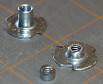
    So far the plastic has held the thread but I have plans to use "blind nuts" if the plastic threads strip eventually.............


    Blind nuts:


    Zitat

    Do you think, the hinges will scuff when you move them?


    I built Lucie (my scratch Warhound) years ago applying aerosol can spray paint to the joints and the paint has not scuffed to date. I will be updating Lucie when I finish this Warlord sometime this Summer and post a thread for the update which will involve magnetizing the armour and the weapons.


    Lucie as she appears today:


    The flash gives her paint a bluish colour


    http://www.dakkadakka.com/s/i/…daae820cccd766b0_6825.jpg (Click the link for a full sized image)


    In natural light she appears gray...........


    http://www.dakkadakka.com/s/i/…2a03738f33977560_6825.jpg (Click the link for a full sized image)


    http://www.dakkadakka.com/s/i/…28a26d29fd9f39d8_6825.jpg (Click the link for a full sized image)

    "It is easier to deceive people than it is to convince them that they have been deceived."

    3 Mal editiert, zuletzt von Blackadderz ()